In the last tutorial, we placed lighting fixtures and equipment. Now we will create the system for the lighting fixtures. Open the model you created in the last tutorial.
Creating the Switch System
Select the left top lighting fixture in the model.
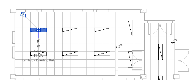
In the contextual tab, you can see the Create System panel. The lighting fixture belongs to switch and power system, that why you can see them both there.

Click the switch button. The lighting fixture is now a part of a Switch System. The contextual tab is now changed to Switch System.
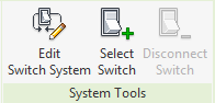
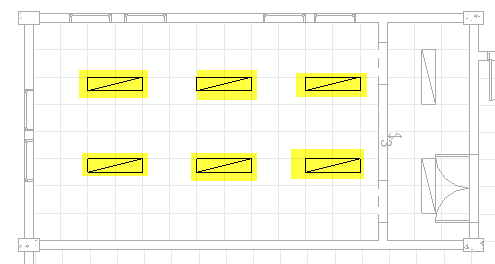
Click Edit Switch System. Add to System tool is active by default. Select the 3 lightings like below.
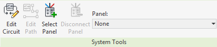
Click Select Switch.
![]()
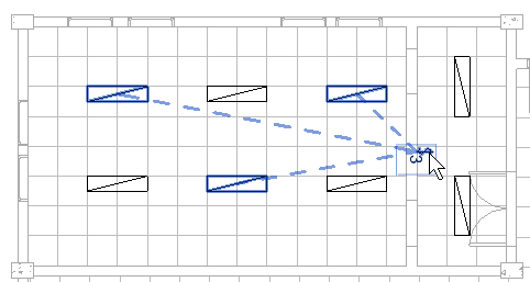
Choose the switch near the room. After you select it, click Finish Editing System.

Place your mouse pointer on the switch and press tab. You should see the system now.
Repeat the procedure to create more switch system. Do it until all lighting fixtures are in a switch system.
This modeling is a basic tutorial, so the exact system is not critical.
Creating the Power System
Creating the power system is similar to creating the switch system. The button names are different, obviously.
Select a lighting fixture in the top left room, then click Power in the Create System panel. Notice that now the Switch system is no longer available.

Now click Edit Circuit. Select all lighting fixtures in that room.
Now click Select Panel from the Contextual tab.
Select the panel in your ceiling plan. In this tutorial, we placed the panel shown below. You may be placed it at a different location.
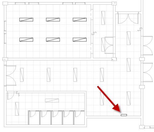
Click Finish Editing Circuit.
Now move your mouse pointer on a lighting fixture. Press tab until you can see the power system. Click your mouse.
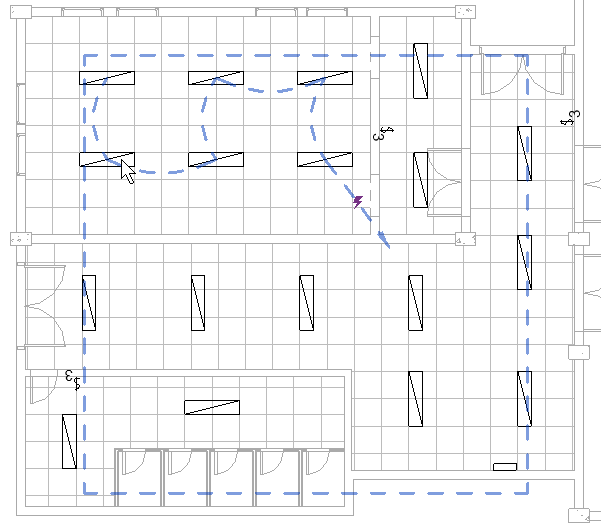
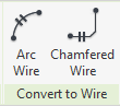
Now on the Contextual Ribbon tab, Convert to Wire Panel, click Arc Wire.
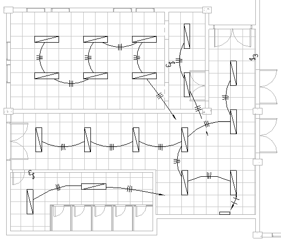
Now you can see the wire is drawn. Repeat the procedure so all lighting fixtures are included in a power system.
Again, the exact design is not critical in this tutorial.
Creating Panel Schedule
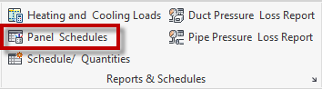
In the Revit Ribbon, Analyze tab, Report & Schedules panel, click Panel Schedules.
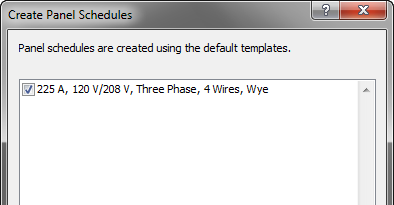
Revit will ask which panel schedule that you want to create. We only have one, so just click OK.
Revit opens the Panel Schedule view below.
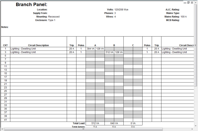
Balancing the Panel Load
We only have a few circuit in this model, but when you have many circuits you may see the loads are not balanced. Sometimes they are very significant.
![]()
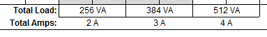
Revit has a tool to rebalance the loads. When you open the Panel Schedule, you can see Rebalance Loads tool on the contextual toolbar. Click it.

Now you can see panel is rearranged and the load is balanced.
Summary
In the Electrical tutorial, you learned about:
- Placing the electrical fixtures and equipment
- Creating switch system
- Creating power system
- Draw arc wire
- Create panel schedule and rebalance the loads